

Jet engines have a lot of moving parts, many of which are bolted together. Bolts need holes to go through, but putting holes in big titanium pinwheels creates weak spots. Weak spots in jet engines are a big reason engineers have jobs.
What did we need to do?
The whole point of this project was to improve the service life of the PW1200 compressor. The team came up with a design, and us structures engineers had to analyze the assembly. A lot of calculations can be done using a simple 2D model. However, some locations require a 3D model to fully capture stress patterns that the 2D model cannot. A bolt hole is one of those features that is more accurately modeled in 3 dimensions.
Bolted flange boundary conditions
To model a bolted flange in any application, there are two key boundary conditions to consider in addition to any other typical finite element model.
- Contact interfaces
- Bolt preload or pretension
Contact
Contact is important in FEA because it helps simulate what is actually happening in real life. If you put two parts next to each other in your 3D model, the computer won’t know what to do with them. In your model, the parts in the assembly can’t see each other unless you tell them where they are or what would happen if they bumped into each other. This is where contact elements come into play. Now, I am far from being an expert on Finite Element Contact Theory, but here’s my layman’s explanation based on the models I’ve built.
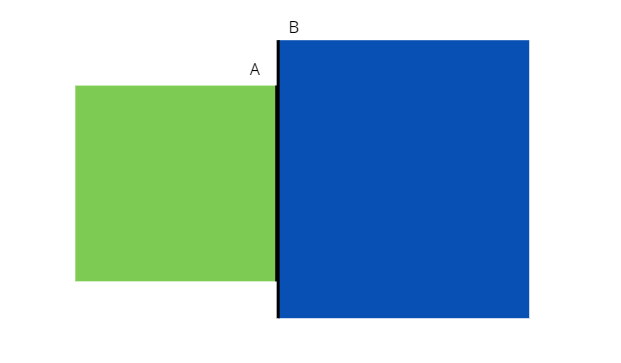
Imagine two blocks that are touching at Surface A and Surface B. At this interface, you have what’s called a contact stiffness value. This value is determined by people smarter than me based off of material and other data. It’s an empirical input in required for this to work. You set up a simple model and apply loads like in the picture below. So now you hit “go” on your model, what happens? Surface A tries to go through Surface B, and vice-versa, but you have that contact stiffness there. That basically acts as a spring, and as soon as Surface A passes Surface B by some amount, that “spring” pulls back on it by some amount of force (F=-kx, remember from high school physics?). So now the computer iterates.
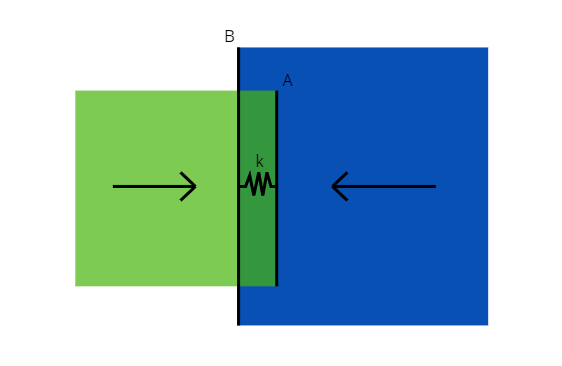
It’s like, “Ok, cool, I passed Surface A by this much, and got this much force. Lemme see what happens if I pass it a little less, what force do I get then?” And it keeps doing that until that force is 0. Why? Because when that force is equal to zero it means that Surface A is line-on-line with Surface B. Which, would be the case in real life when these two blocks came into contact with each other.
That’s cool and all, but isn’t it a lot of math and computing time? Why not just tell the computer, “Hey, Surface A moves with Surface B, no matter what.” You can certainly do that in FEA, this is known as “bonded contact”. In fact it’s very easy, but it robs you of a few things. First, part of this whole analysis is to mimic real life and see if these parts are going to accidentally come apart. No one wants jet engines to accidentally come apart. And second, this doesn’t allow each surface to slide along the other surface with friction as it would in real life. So, the method described above is known of as “contact penetration,” and that stiffness mentioned earlier is the “penalty stiffness.” In other words, there is a penalty for penetrating the surface. Not only is this important when you have a model that simulates an assembly of multiple components, it is also important when you clamp them together with bolts.
Bolt Pretension
So now that the flanges, nuts, and bolts in the model know where each other are, we can pretension the bolts. The designer of this LPC assembly determines a bolt load spec. This tells the folks putting the thing together how hard to turn their wrench, and it tells me how hard to squeeze the flange together in my model.

While it doesn’t look like one, the bolt is a spring. When you torque the nut, that spring stretches, and it wants to retract back to its original length with some amount of force. Again, F=-kx. Remember the forces on the two blocks? In this case that is the bolt squeezing the flange together, otherwise known as “bolt pretension.” Lucky for us engineers, most FEA softwares have built in tools to simulate this rather simply.
Putting it all together
Pun intended. The combination of bolt pretension and surface contact described above is critical if the goal is to simulate the loads these parts are going to see in real life… and that is exactly the goal. Now that the model is assembled, all that’s left to do is spin it up and evaluate the stresses and temperatures. With those numbers we can predict the service life of the new design, and confirm that the changes we made improve the design.
